In the above video, the second plane locks two degrees of freedom.
#DATUM IN DRAWING SIMULATOR#
Secondary data should make two points of contact with the data feature simulator and should lock two degrees of freedom. The primary datum is usually shown as Datum A Secondary Datum In the above video, you noticed that the first datum locks three degrees of freedom. The primary datum should make three-point contact with the datum feature simulator and lock three degrees of freedom. This whole phenomenon of locking 6 degrees of freedom is called the 3-2-1 rule. So in this case, the first datum is called Primary datum, the second datum is called secondary datum and the last datum is called a tertiary datum. As soon as we assemble with the third datum, the last degrees of freedom are also locked.

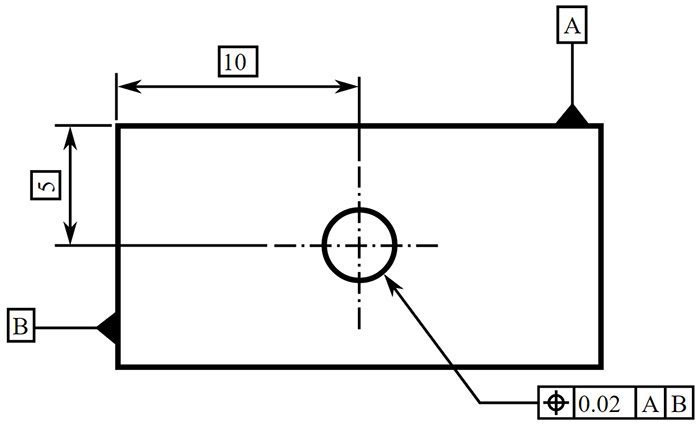
When we assemble with the second datum, two more degrees of freedom are locked. In this video, you may notice that, as soon as we assemble the part with the first datum plane ( Primary datum), 3 degrees of freedom is locked. To understand datum precedence, let us watch the below video. Unless we lock all 6 degrees of freedom, a body is not locked and not considered stable. Three transnational ( X, Y, and Z) and three rotational against X, Y, and Z. There are 6 degrees of freedom a body can move. Based on datum precedence, datum’s are divided into the following types. To find out the level of importance, datum precedence is used. If you see the below example, the left side surface of the block is a datum feature as it is establishing datum “A.” Also, the second hole is the datum feature as the axis of that hole in the datum ” B.”ĭatum precedence decides which datum is more critical from a part function point of view. What Is Datum FeatureĪ datum feature can be defined as an integral feature of a part that can be established as a datum.

If we show the datum in the drawing, the supplier will understand which surface is important, and accordingly, they will measure. The reason is supplier has to assume which surface is important. So we noticed that without datum, there are high chances that a part may get rejected. The same goes true if the left side surface is important and the supplier measures the part like “Scenario-2.” But if the supplier measures the part like” Scenario-1″, then the part will not get assembled and will be rejected. Let us assume that the bottom surface is important for mating with other part and need to be flat.

Now the manufacturer can measure those surfaces in two different ways, as shown on the right side. In the example, the left side image shows a typical dimension of a block. To understand why datum is required, we need to look into the below image. See this below example where all the hole positions are referenced from a datum named “ A“ Datum needs to be chosen carefully because choosing the wrong datum may cause the part to get rejected considering form, fit, and function. So datum acts as a reference point or an anchor for almost all geometrical tolerances and dimensions.

Types Of Datum shown in engineering drawing.


 0 kommentar(er)
